
A bit of history (part 24) – Induction time
- ainsworthashley
- Dec 14, 2017
- 18 min read

The next part of this has been much harder to write, there are so many aspects that I’ve wanted to share, but keeping a coherent “build thread” narrative going at the same time is challenging. In the end I’ve simply decided to write it and see where the pieces land, so apologies in advance for the long one, it could (and probably should) have been broken down into separate updates, but, well…it isn’t…sorry!

First I have to acknowledge one of the true heroes in my life, and a key foundation to this whole project: my Dad. I can’t begin to describe the level of respect and love I have for the guy, he has been a proper inspiration to me, and I have spent my life aspiring to be more like him.
Dad’s approach to all things engineering is what has allowed me to be able to play with cars, he is fiercely engineering based, and his first assumption when faced with any complex system is that it can (and will!) be understood, and any problems can thereby be resolved. So instead of me treating cars as complicated “black boxes” like the majority of people who simply use them, I have also been gifted the vision that if there is a problem, get in there and fix it!
Although we have not always seen eye-to-eye, Dad’s approach to “training” me has always been to give the bare minimum of advice required to get started, and then to leave me to work the rest out for myself. At times this has been the cause of much frustration as he then comes back to point out where I’ve made mistakes, but in hindsight this has nurtured a very hands on, learn through experience approach in me, and as a result I’ve developed life-long skills that can be applied to many situations, instead of just having been told how to fix a one of problem.
So in a nut shell- thanks Dad, I owe you and even if I don’t say it very often, I’m extremely grateful for everything you’ve taught me!
So…ahem…mushy stuff aside, why mention this? Well one of the key skills Dad has helped, and encouraged, me to pick up has been machine work, specifically on the lathe (and more lately on the mill). And it is the development of my lathe skills that has driven a lot of what I’m about to document, indeed the real reason I did a lot of the following work was to have excuses to use the lathe, and with literally hundreds of hours of machine time under my belt now, I am hugely grateful for the opportunity to do so.
Not to mention that the machinery is all Dad’s, and he has had to put up with me spending hours locked away in his workshop making chips and swarf…and probably (definitely) not tidying up as much as he would like…sorry Dad!!
Right- so onto the project…
Collecting parts
Last I left things I had a freshly built engine and gearbox, a new turbo, and a new exhaust system to help the turbo breath…the next part of the system to sort was the induction system: so air into the turbo, charge cooling and air into the engine.
I had previously used a boot mounted Radtech charge cooler (air to water charge cooling), but had concerns that the relatively small size of this core was acting as a restriction to the system, and thus limiting the top end power levels it was capable of. This was even more of a concern now that I had significantly increased the turbo size, and was anticipating smashing the 400hp limits of the Radtech unit (according to internet wisdom).
First things first, I decided I wanted to keep the charge cooler out of the boot this time, not for space, but more so I could reduce the length of intake pipework the air has to make its way through before entering the engine. I also wanted to significantly over-spec the cooling abilities of the system with no, or little, increase in pressure drop across the charge cooler system (i.e. I wanted to preserve as much of the precious boost pressure the turbo was generating, as well as maximising the temperature drop of the air before entering the engine).

A bit of help from Peter and I followed the advice he had been given by Pacific Racing in the US, namely to over-spec the core size and significantly increase the flow rate of water through the system. So I purchased a proven high horse power capable charge cooler core from Precision, specifically a single pass 1000hp rated unit which they demonstrated truly minimal pressure drops across.

To go with this I also purchased a massive water pump (specifically a Rule marine bilge pump); this is an area worthy of a quick discussion…
The concept of increasing the flow rate of coolant through the charge cooler system makes sense in terms of moving the heat from the charge cooler core as quickly as possible, thereby maximising its ability to pull heat from the air flowing through it. The heat needs to then be pulled from the coolant as it flows through the radiator at the front of the car, and transferred to the air passing through it…and herein lies the potential problem: if the water is flowing too quickly through the radiator, will it have sufficient chance to be cooled in the radiator??
And to be honest, I don’t know the answer! It was raised as a concern when I spec’d these parts, but I had to take some confidence in this system being proven in very high powered drag cars already…so to an extent I would have to suck it and see what happened, if I experienced issues I would deal with them further down the line…

So with the main cooling parts of the system identified, I then had to face the consequences of my plans: I needed a new inlet manifold…the one I had presented the throttle on the wrong side of the engine bay for my plans, and was not going to be easy to modify to accommodate the changes I had planned. Not long after I decided to buy a manifold from Jeff (RacerX Fabrication) with no throttle on it, probably not the best manifold ever, but a solid design that would certainly support my plans without having to get into complex inlet runner design calculations.
In changing inlet manifold I also had an opportunity to upgrade the throttle attached to it, my prior one being a 2.5 inch diameter unit, which just didn’t make sense in my mind when all the rest of the pipework was 3 inch.
Added to this (thanks to an evening in the pub with my brother), I decided to do away with a cable operated throttle, and switch to an electronic drive by wire unit instead. The rational for this was to allow us (at a later date) to play with mapping the throttle pedal: this would mean a non-linear relationship between pedal position and throttle plate angle.
Why? Well- in theory you can then create a more linear relationship between engine output and pedal position…
With a turbo charged engine, where you have to wait for the exhaust gases to spool up the turbo before you see increased engine output, it is not uncommon to see relatively small increases in engine output with the first (say) 60% of throttle pedal travel, and then the bulk of the transient in engine output in the top (say) 40% of throttle pedal travel.
By plotting the engine output levels seen at different rpms, at different throttle plate angles, you can then match the throttle pedal travel to this relationship- meaning that for a given % increase in throttle pedal movement, you will see a corresponding % increase in engine output….in theory!

This is something we are still to have a go playing with, but it’s nice to have the capability to play with interesting ideas anyway…so a drive-by-wire throttle from a Toyota 2UZ-FE 4.7l v8 engine soon arrived, with the added bonus of being a true 76mm internal diameter. Happy days!
With the necessary parts purchased, it was then time to start putting it altogether into a coherent induction system; starting at the turbo…
Compressor Housing
With the last running of the car I had struggled with the silicon pipe from the turbo to the charge cooler pipework failing due to heat fatigue…it sits close to the exhaust manifold, and is simply unable to cope with the extremes. This time round I wanted to deal with this by replacing the silicon joint with a Wiggins clamp fitting, which allows two pipes to be joined with an aluminium clamp, the resulting joint be able to articulate, and deal with vibration.

Off I went and ordered the relevant Wiggins clamp together with the weld on flanges the clamps use, expensive- but hopefully solving the problem once and for all…
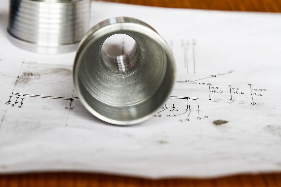
Unfortunately I managed to order the wrong size to mate to the compressor housing on my turbo, but in doing so I got a chance to take a close look at how the flanges are designed…which got me to pondering whether I could make my own weld ferrules on the lathe. They really didn’t look that complicated, and this would mean I could not only make the size I wanted, but I could also add internal tapers to allow the air to transition smoothly from the relatively small outlet of the turbo, into the full 3 inches of the pipework.

Much thinking and planning later, including re-learning trigonometry, and I had the design of what I hoped to make…nothing for it but to start honing my lathe skills and get stuck in! I purchased a decent set of index tools, with carbide tipped inserts with the correct geometry for aluminium, and it wasn’t long until I had made my initial cuts in the fresh aluminium round bar.
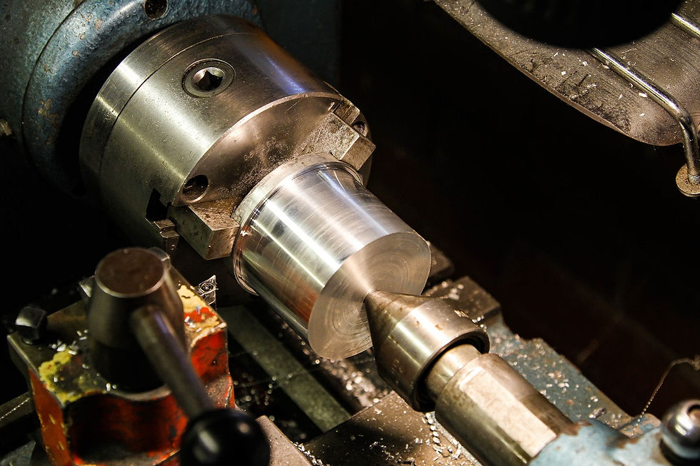
Then it was time to cut the 4mm channel where the o-ring seal sits, and for this I needed my own tool. Apparently this is half the fun of lathe work- making your own tools out of hardened tool steel...and her she sits:

And luckily it seems to have done the trick nicely, o-ring channel cut exactly as wanted:

Second edge cut, and the 45 degree termination cut where it would weld onto the turbo:

Then onto the job of boring the middle, I worked up drill sizes until I got to this bad boy:

Then out with the boring bar and the internal cut to the required angle of taper, and we have a finished product waiting to be cut off:
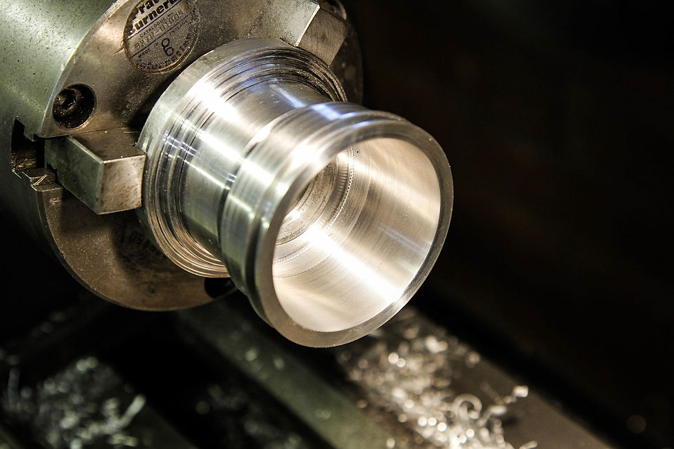
A good learning exercise, and I was really pleased with how the new tools were cutting (except for the final pass on the internals where I left 1/100th of a mm to cut in an attempt to get a nice finish and it ended up chattering a bit). I was also trying to work out how to take the small amount of play I was seeing in the compound slider, which I later realised you can tighten down further.

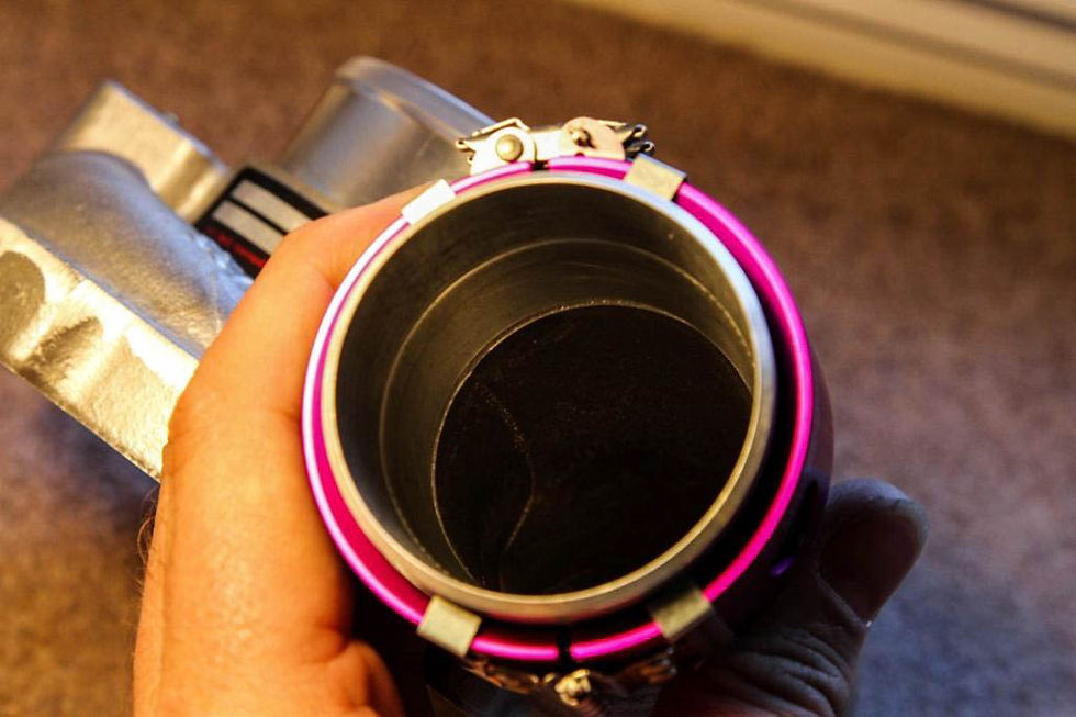
Rinse and repeat, and I ended up with the two custom Wiggins clamp ferrules…I remember feeling pretty proud of my efforts. The plan for the finished product would then be something like this, with a 90 degree bend straight out of the turbo in 2 1/8 inch OD pipework, which matches the Wiggins clamp nicely:

The finished pieces:

The first one matched the turbo inner diameter:
The second one matched the boost pipe inner diameter:
With a smooth even 4.4 degree taper between both ends:
Chuffed!
Well…until I committed to the plan and chopped the end off the compressor housing of my brand new (very expensive) turbo…and realised the housing was tapered inside, and not completely round inside…

D’oh!
So some more lathe time later, and I had knocked up a new clamp that tapers down to the correct size. I would finish the port matching up by hand once it was welded on there, and I deliberately left the clamp on the small side, that way when I ported it 95% of the material will be removed from the clamp to replicate the stock compressor housing shape as far as possible.

Hot Pipe
Given the above, you can see I had already made a start on the pipework that would run from the turbo to the charge cooler…the key issue here was the 90 degree turn required in a short space in order to avoid fouling the engine lid. With the compressor housing modified, I could have a proper measure up and settle on a design for the rest of the pipework.
I measured up most of the run from the turbo to the charge cooler, and the plan was a 2 & 1/8 inch, 90 degree bend straight out of the compressor housing. This then tapers up to 2 & 1/2 inch, and through a 45 degree bend, which then tapers up to 3 inch to match the inlet to the charge cooler.
The basic aim was to avoid any sudden jumps up in pipework size to try to maintain as much laminar flow as possible...totally OTT, but a great excuse for lathe work...!
I quickly made the first taper pipe up (more lathe time!), and the set up looked like this:

I then finished the final piece of the pipe, which tapers up to ~69mm inner diameter to match the charge cooler, and I left a flat on the end for the Samco silicon pipe to seal on (which is a straight reducer from 76mm to 70mm). I also added some additional very shallow grooves on the flat to help the silicon to grip.

I left a 10mm gap between the exit of this pipe and the entrance to the charge cooler, together with the Wiggins clamp this would hopefully provide room for enough movement between the engine and chassis.
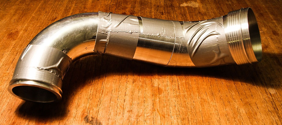
The final pipe taped up and ready for tig welding:

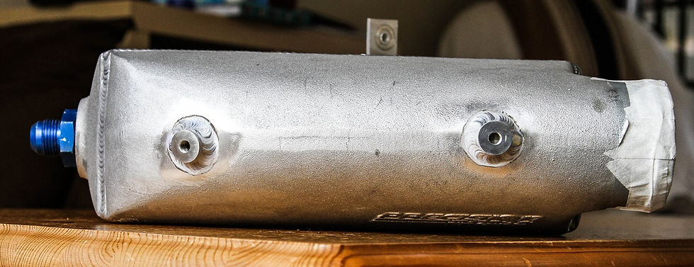
Charge Cooler
Time to attack the charge cooler itself next: the issue here was the size of the thing, and trying to keep it as far away from the exhaust manifold (and heat) as possible.
The first issue was the 1” NPT threads already cut in the cooler for water pipes only let the Goodridge fittings screw in so far:

In order to get the charge cooler as close out to the side of the car as possible I wanted these fittings in as deep as possible, but running a tap in was impossible as the water core inside was in the way…so time for some bushcraft mechanicing: out with the angle grinder and we have a cut down tap:
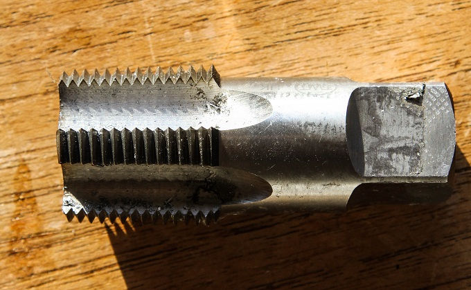
After some cutting, this meant the water fittings now sat further into the core, (with the internal ends trimmed down to match), and still seal on the taper in the female thread.

The other cunning plan was to reduce the length of the air inlet/ exit pipes, again allowing the pipework to keep further away from the exhaust manifold…so out with a hacksaw and some masking tape:

Then in order to avoid the boost pipes popping off when under pressure, I created some rings in polyester resin for the hose clamps to tighten down behind:

Inlet Manifold
It was now time to make up a plate for the new inlet manifold that my chosen throttle body would mate to, this adapter plate would then be welded to the open end of the manifold itself.
So one piece of ½” aluminium plate, a throttle body, and time to measure, mark and drill the four mounting holes. These all needed to be blind (to keep the manifold sealed), and then threaded in m8 flavour…

The easy bit done, I then marked up where the throttle port itself needed to go through the plate, and then onto the drill press again…after a ‘while’ we have a hole through the plate. I then bolted the throttle body up to the plate and liberally used the belt sander and various other porting tools to match the plate to the throttle.

I finished this later with finer grade wet and dry paper for a nicer finish.
Feeling chuffed, I thought I would simply bolt the manifold into the engine bay, temporarily attach the throttle body, and have a final measure up for the pipework from the charge cooler into the manifold….or so I thought…
Unfortunately it transpired that the throttle body would not fit, and was fouling on the rear engine bulkhead….ooops!

A quick phone call to the experts and the day is saved, apparently it really doesn’t matter in what orientation the throttle plate opens in relation to the runners into the head: the plenum being plenty big enough for the air flow effects from the throttle plate to diffuse before hitting the runners.
Crisis averted, I simply needed to rotate the whole throttle body by 90 (or even 180) degrees…luckily nothing had yet been welded!
As it turned out I did have to remake the adapter plate anyway, as when I rotated the throttle body by 90 degrees, the port was no longer in the middle of the inlet into the plenum…but the second plate was easy having already done it once…
Welding – turbo & hotpipe
Before I went any further I decided it was time to actually weld the pieces I had already made, that way any distortions that might come into play as part of the welding process could be adjusted for when I made the final piece of pipework.
And at this stage we get to meet another character in this story, namely my very good friend Bob Hall. Now I met Bob down at Symmonds Yat, on the river Wye near Ross…I was getting changed after a kayaking session, and noticed another paddler changing with a bright orange van with “Concept Racing” on the side.
Being interested in cars, and paddling, I figured I’d say hello…and it turned out that Bob owns and runs (with his partner Claire) a bespoke, custom fabrication business in Ross on Wye, specialising in aluminium fabrication for the motorsport industry. He makes all sorts from radiators, dry sump systems, to charge coolers and historic race car repairs.
I didn’t think much of it at the time, you meet a lot of folk who are into the “race” industry, but he did seem a nice guy, and seemed willing to take on TIG welding projects…ideal, a local welder!
I was initially a paying customer, distracting Bob and Claire from their main paying business to weld up my odd little creations, and eventually Bob got interested in some of what I was doing. I was going through a rough patch at the time, with ~12 months off work for extreme anxiety and depression, and I spent a large chunk of that time in Bob’s workshop watching, and trying to copy his fabrication skills.
He very kindly taught me a lot of skills, and has even attempted to teach me to TIG weld (with limited success so far!), but more importantly he has become a rock solid friend, and really helped me get through some dark times. It was amazing therapy to be able to go and bury myself in making stuff at his workshop and forget my worries for a while!
Anyhow, I’ve got lots of adventures with Bob to recount, he’s helped me a lot with this project, and in turn I’ve done my best to help him as much as possible with his project…but that is a subject for a future post…stay tuned!

So it was with Bob’s help that my inlet manifold was finally finished with my throttle body plate being welded in place, check out the welding- it’s almost like Bob knows what he’s doing!

He also welded my Wiggins clamp flange onto my turbo compressor housing:
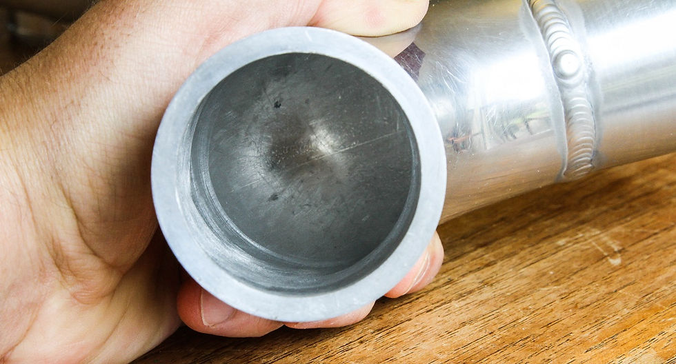
I then ported the exit of the compressor housing to blend the Wiggins flange into the original casting, I was pretty happy with the results:

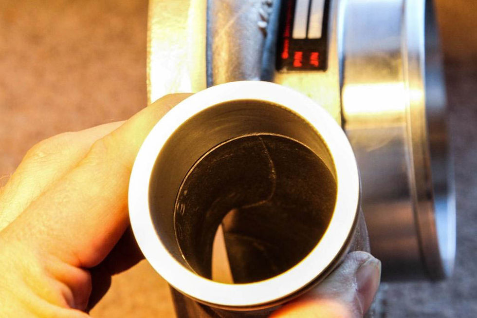
Finally Bob started welding my hot pipe assembly, which I asked him to do a single section at a time so that I could reach inside the joins and remove any mismatches and bleed through weld, probably totally over the top- but having gone to such pains to create a nice pipe, I wanted the insides as clear from obstruction as possible.
Here I am part way through cleaning one join up, you can see the weld bleed through- normally you would manufacture the joints so one end slipped inside the other to avoid this, but I was yet to learn this skill!

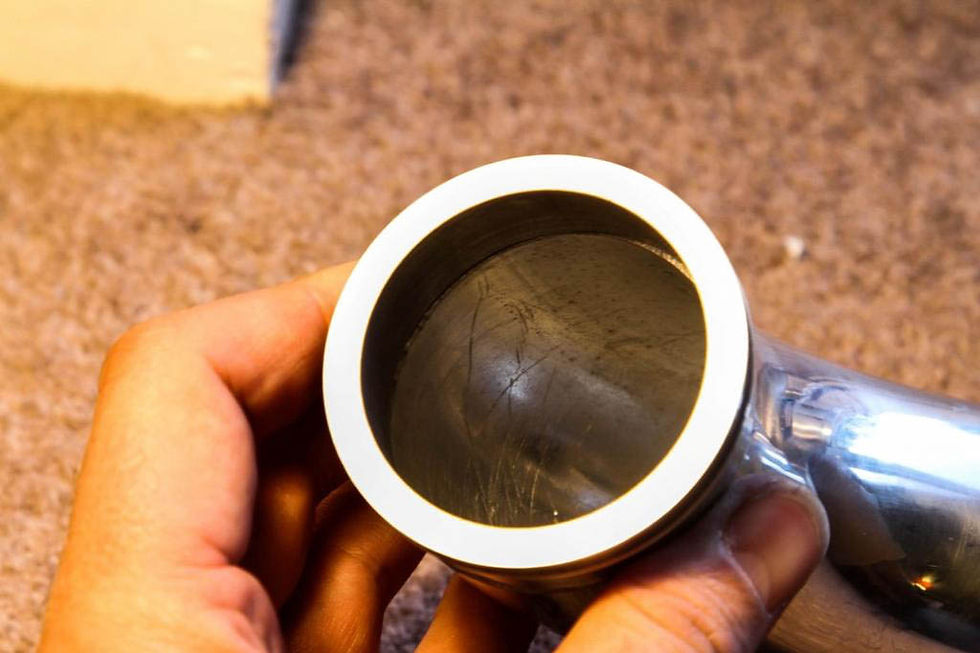
And after cleaning up- a lovely smooth bore for lots of boost to pass through smoothly…
Happy days...you really would not believe how many hours I have invested in this one, small piece of pipework!! Such is the price of learning with an obsessive level of attention to detail...

Mounting charge cooler
Now that I had the main pipework into the charge cooler finished, I could start on the mounting points for the charge cooler itself…I kept this pretty simple.
One drop down bracket to secure to the chassis mounting point for the original air box:

Then a couple of weld on bosses (more lathe time!) to mate to a drop bracket from the chassis at the back of the core, and a rising bracket from just above the gearbox mount to the front of the core.
Pretty simple, although it did take a bit longer than this description would suggest!!

Cold pipe
With the charge cooler position reasonably finalised, I could then turn my attention to the final piece of this particular puzzle: getting cold air out of the charge cooler and into the inlet manifold. I had initially planned to do this in a single aluminium pipe, but came up against a couple of problems.
First the outer diameter of the exit from the charge cooler was smaller than that of the throttle body, so the pipework would need to taper up (not really an issue, just a complication).
Secondly, given the offset between the charge cooler and throttle body’s relative positions, two 90degree aluminium bends (with sufficient straight pipe at each end for silicon joiners) were simply too big:

So to get round this problem I opted to use two 90 degree silicon bends instead, I could cut the straight sections at slight angles to increase the rate of bend, and as they went over the outlet of the charge cooler, and the entrance to the throttle body, I saved the extra straights needed for additional joiners.

So all I now needed to do was make up a simple straight tapered pipe to join the two bends, and (yep you guessed it) that meant more time on the lathe…a LOT more time…a lot more time boring…


I was really happy with the end result, a nice light weight but solid piece of tubing…

In order to finish it up I just needed to cut a hole in the side of it, and attack a blow off valve flange to match the pipes profile, before letting Bob melt the two together…and then we end up with a completed cold pipe:
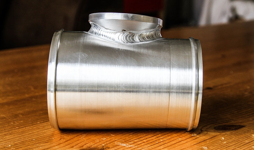
Feels like progress!

Water pipes, pump and adapters
Using stock coolant lines, heat transfer concerns, 19mm Goodridge hose, pump location, water pipe adapters 38mm, swirl pot, testing fuel tank fitment
One of my key concerns with the prior charge cooler install (aside from the size of the thing!), was that the rubber water pipes (that transferred the water between the front radiator and the rear mounted core) were cable tied to the engine coolant lines (that transfer hot engine coolant to and from the main radiator).
Why did I care? Well the engine coolant system is typically dealing with temperatures around 100c, whereas the aim of the charge cooler system is to keep inlet air temperatures as low as possible, and certainly nowhere near 100c…so by running the water lines next to each other you are encouraging heat to transfer from the engine coolant system into the charge cooler system, which is only ever going to reduce the efficiency of the charge cooling.
In order to try and isolate the two systems this time round, I wanted the charge cooler water lines as far away from the engine coolant system as possible…and so I elected to run them on top of the fuel tank, where the stock environmental control (heater) water lines would be (which I had now made redundant by removing the environmental controls).
I did initial consider using these stock water lines above the fuel tank, they being approximately the same diameter of the 19mm water lines I planned to use, but on closer examination I wasn’t totally happy with how the bends had been formed, which had resulted in the internal diameter closing up. So I elected to use Goodridge water hosing in the end.
Next up I had to work out how to connect the 19mm hosing to the 38mm inlet/ exit of the water pump I had purchased, and planned to mount in the front of the car. And (yep you guessed it) any excuse to use the lathe, I decided to make myself some adapters…

The first iteration was purely functional, but once I had them in my hand I couldn’t help critiquing the design, and came up short on the amount of material (and hence weight) left in there…
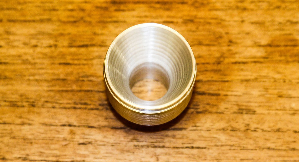
So onto my most ambitious piece of lathe work to date…and probably one of my better achievements at this stage. I remember being hugely chuffed to cut two of these out first time, no mistakes..and they rang like bells when you hit them they were so lightweight!

The middle was my first attempt, which worked but was too bulky. The left shows the Goodridge push fitting design for the 19mm hose with three barbs to hold the pipe. And finally, on the right we have the completed second design without a square shoulder, and incorporating Goodridge’s design.

First attempt: 46g
Second attempt: 24g
So approximately a 50% saving in final material…not bad for two adapters no one is ever likely to see again!!
Final install of inlet manifold
At last I was at a position to build up the inlet manifold ready for final installation, which involved fitting studs to mount the throttle body to one end:

And mounting the required sensors at the other end, being air temperature and manifold pressure. There was also a fitting to provide vacuum assist for the brake system, and a couple of additional ports that I made blanking inserts on the lathe for.

Finally, bearing in mind I was using a newly worked over cylinder head, I wanted to double check port alignment from the manifold and into the head…which showed that I could remove a chunk of material from the manifold to properly match the two:

Which I set about doing, and soon had a nicely port matched inlet manifold ready to bolt to the engine:

Not too shabby…

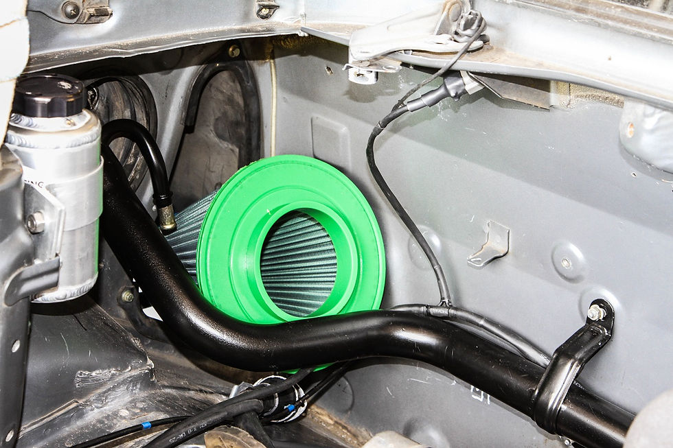
Air filter
Finally in this update(!), it was time to think about getting fresh, clean air into the turbo…again the focus was on trying to maximise the efficiency of the setup, and there was no point in letting the turbo suck in hot engine bay air if we were focussed on keeping the inlet air as cool as possible.
To this end I wanted to force feed air into the filter of my choice by locating it right in the engine bay side air inlet pod, which meant running the induction pipework under my newly mounted charge cooler.
To facilitate this I had a slight modification to make to the main fuel tank filler line, namely cutting the breather line off:

I then welded it back in place in a new orientation, and so keeping it out of the way of the proposed route for the new induction pipework:

I finished this off with polyester resin to ensure any pinholes were sealed, then sprayed it down in etch primer, and finally matt black…

With the fuel line out of the way, it was a quick and easy job to blend a couple bends of 4 inch aluminium pipework together to navigate their way from the filter to the turbo, which Bob kindly melted together for me:

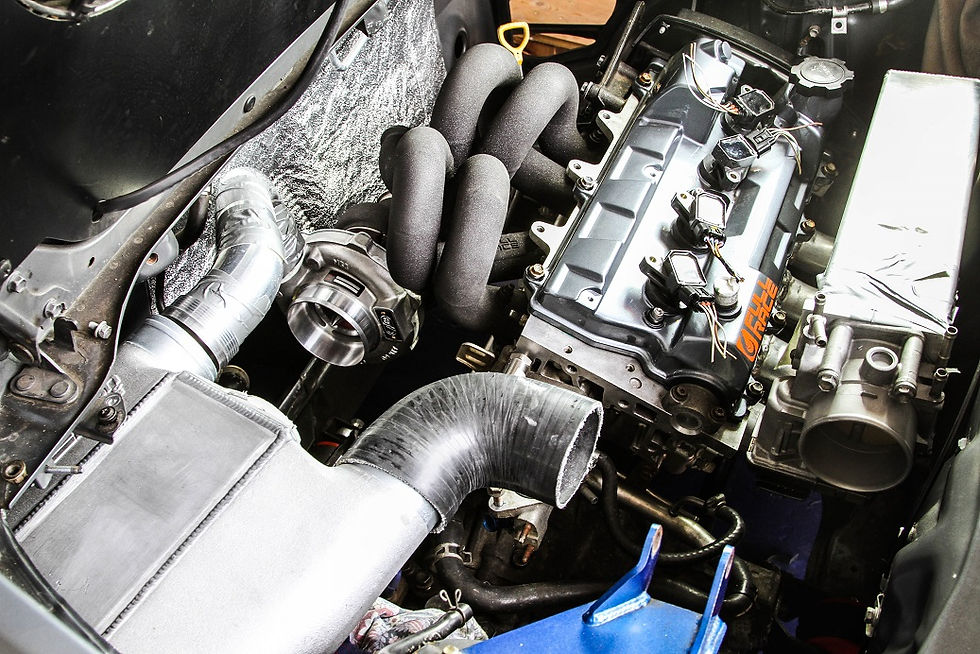
This then sits about here:

So in theory a free flowing, unobstructed supply if fresh air from outside of the engine bay for the turbo to suck up and compress…

The end of a long update
Well, that was a bit of a bigger update than I had planned! Still, it knocks out a chunk of the modification work in support of my new plans…and we now have a new turbo which is supported by an improved exhaust system, and a (hopefully) improved induction and charge cooling system.
I was also properly stuck into the project now, and really enjoying myself…my mindset had really changed (thanks to Dad and Bob’s influences) into a belief that you can make anything you want, as long as you can picture it in your mind first…and this is certainly an approach I have now fully adopted in everything I do engineering and mechanically.
Definitely guilty of having way too much fun, and getting far too carried away…but that’s what project cars are for isn’t it? The fact that I learn something new at each step is a huge bonus as well…
Comments