
A bit of history (part 21) – Let the build begin...
- Nov 7, 2017
- 5 min read
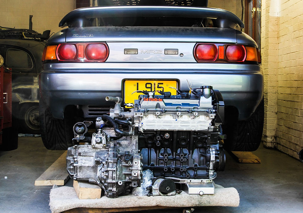
Finally it was time to think about getting the engine and gearbox back in the car again following it’s full rebuild be Peter, and the resolution (hopefully!) of my mysterious whirring noise…along the way I had also decided on a “few” tweaks to the set up as a whole, and I needed the engine back in the car to engineer these. Rest assured- much more detail to follow on these!
First on the list was to ditch the old-school distributor ignition system, having upgraded to MoTeC to run the engine, it seemed a waste not to give the ECU full control over ignition timing. As part of this I decided to install a set of coil on plugs- an individual ignition coil for each spark plug, and so replacing the OEM distributor and single ignition coil.
The Toyota 1ZZ engine uses coil on plugs, and as it happens- these are a pretty good fit on the 3S engine given a bit of minor fettling, (apparently the 2ZZ coils fit as well, but in testing the 1ZZ units seem to be more robust under the extremes of forced induction).
To make this system work optimally the ECU requires two pieces of information: the position of the crank shaft in its rotation, and the phase the camshafts are in (remembering that the crankshaft rotates twice for every rotation of the camshafts).

One common method to measure crank position is to bolt a trigger wheel to the outside of the crank pulley, this has teeth cut into the outer diameter, typically with one tooth missing. A hall-effect, or magnetic sensor then detects these teeth as they go past it, and the ECU can use this signal with reference to the missing tooth to know very accurately where the crankshaft is in relation to top dead center.
I had initially planned to go down this route, but I spotted another engine Peter was building, and this utilised a stock Toyota crank sensor and trigger system that was far neater, and hidden away under the timing cover- thus removing any risk of an external trigger wheel coming loose, or being fouled by detritus (such as gravel from a gravel trap!).

The setup up utilises the 5S oil pump with integral crank sensor (note with the oil pump drive swapped for a later 3S version to accommodate the 3S timing belt, which is a different length and possibly pitch to accommodate the twin camshaft design head). In relation to this I used a 3S Beams engine crank timing belt sprocket, which has the teeth cut into it…a really nice solution that looks properly OEM once installed.

So that takes care of the crank reference signal, next up we need a cam shaft synch signal- which is far simpler, only a single tooth is required for the ECU to identify which part of the engine cycle the camshafts are in. There are obviously a number of ways of doing this, but I took the easy route of using a simple disk with a single tooth cut into it, bolted to the end of the exhaust camshaft with a cherry sensor to detect the gap. Not quite as OEM as the crank signal setup, but it serves the purpose!

In anticipation of re-hanging the engine I cleaned up the existing engine mounts, and upgraded the longitudinal inserts to Speed Source polyester, the idea being to stiffen up the resistance to engine rotation under hard acceleration. At this stage I opted to leave the cross sectional mounts as stock, although I would like to modify these at some point simply to remove the excess weight they represent…

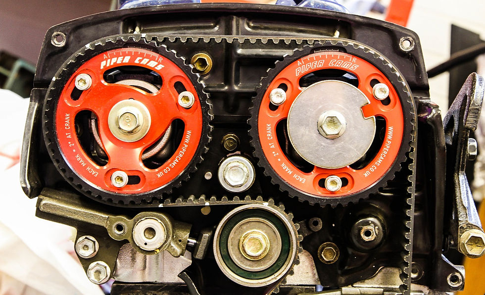
Next up engine and box were happily re-united, and I moved onto swapping on the of the cam pulleys over- one of the Piper pulleys Peter had donated to me when we spotted my Catcam pulleys were not running true had some slight damage on it, and in the interests of being overly concerned with the small details I opted to swap it out for a new one. The main issue was insuring I preserved the cam timing, the pulleys being vernier, and it was a simple case of matching the adjustments on both pulleys and making sure the belt went back in the same position.
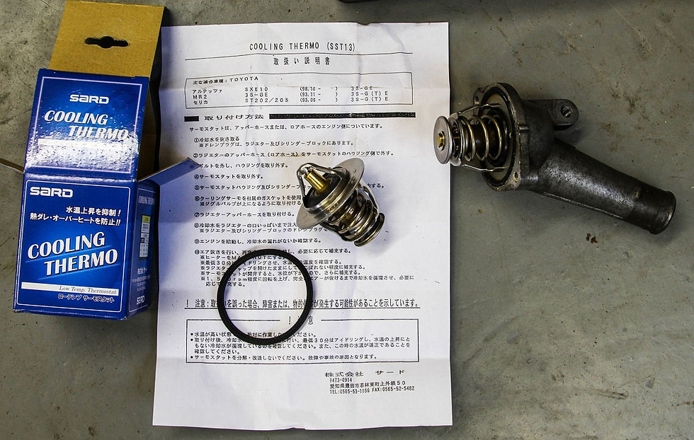
Cue final install of cam synch sensor, and we are ready to think about throwing this lot back in the car…just one final adjustment: I decided to swap in a low temperature thermostat. This may be a controversial one, but the reasoning in my head struck me as sound!

Basically I had been chatting to my brother in the pub and we got talking about some dyno testing he had been doing, they were running an engine on an engine dyno and were in control of the coolant temperatures the engine was experiencing through external cooling. The long and the short of it was that, contrary to what you would maybe expect, the engine made more power at lower coolant temperatures.
So my rational was that by using a thermostat that opens at 68c instead of 80c, this would allow the cooling system (assuming it was capable!) to maintain a lower temperature of coolant in my engine, and so putting me in the scenario of slightly higher power…! This may have been wishful thinking, and to be honest any change in output is probably in the noise, but why not give it a try?
Anyhow- that done, it was just a case of performing some dressing up for the engine- spraying the timing covers, and having my first go at shooting some “real” paint…
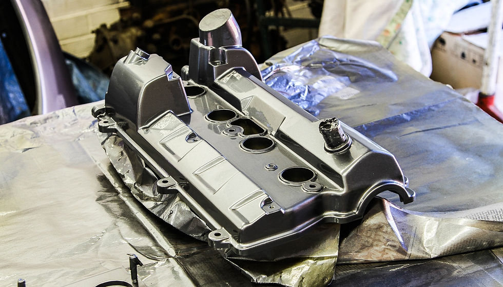
The big lessons here were (1) my car is not quite the stock Toyota colour I thought (the paint shop having to take several attempts to match the colour on one of my headlight covers for me!), and (2) reaffirmation that I have a lot to learn when it comes to spraying!!
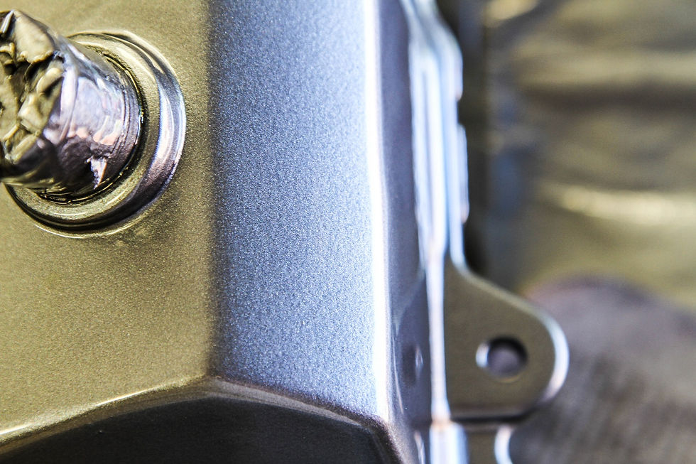
That said I jumped in complete with a separate forced air breathing mask and laid two coats of etch primer before throwing some of my new Steel Mist Grey at the cam cover, followed by a few coats of lacquer…and I have to admit, I was pretty proud of the results.

Finally it was time to get the engine back in the car, which following all the build-up, was actually a bit mundane, and completed all too easily and without fuss…happy days I guess.
In order to complete the install I decided to replace the hydraulic line to the clutch slave cylinder, I had accidentally stretched the stock one last time I dropped the engine, so it seemed a good excuse to swap in a Goodridge braided line instead…and whilst I was there it seemed rude not to clean and paint the whole assembly…

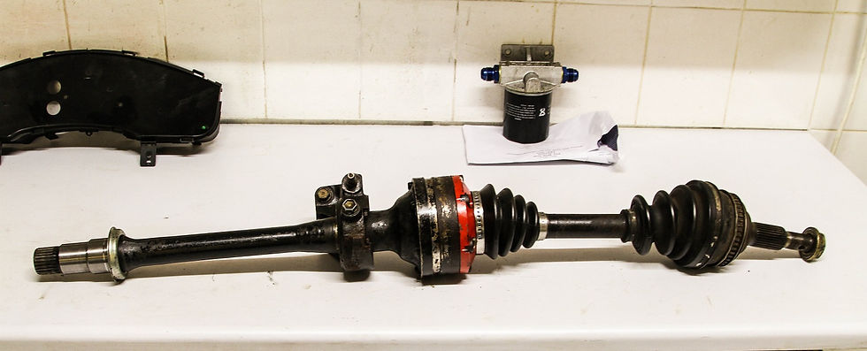
Next up I had to address the driveshafts: the newly built gearbox now housed a Quaife ATB differential, which they have designed to fit “all” MR2s, and as such had the spline design from the earlier MR2 drive shafts in it. My driveshafts were of the later variety, so I obtained a pair of earlier shafts and stole the inner shafts from them. These I then assembled with the outer shafts from my original units, together with the uprated CV joint bearings/ cages…and we have a pair of Frankenstein drive shafts ready to lay down some torque…!
With the engine in the car I could now start to implement some of my “new” plans for the build…the first item being a trip to PTR Exhausts near Silverstone…..
Comments